- 您现在的位置:买卖IC网 > Sheet目录218 > D1U-W-1200-12-HA2C (Murata Power Solutions Inc)POWER SUPPLY 1200W AC/DC 12V
D1U-W-1200-12-Hx Series
AC/DC Front End Power Supply + S1U Power Shelf
CONTROL SIGNALS
Status
LED
I 2 C Registers
EMISSIONS AND IMMUNITY
Characteristic
Harmonics
Voltage Fluctuation and Flicker
Emission Conducted
Emission Radiated
ESD
Electromagnetic Field
Electrical Fast Transients/Burst
Surge
RF Conducted Immunity
Magnetic Immunity
Voltage dips, interruptions
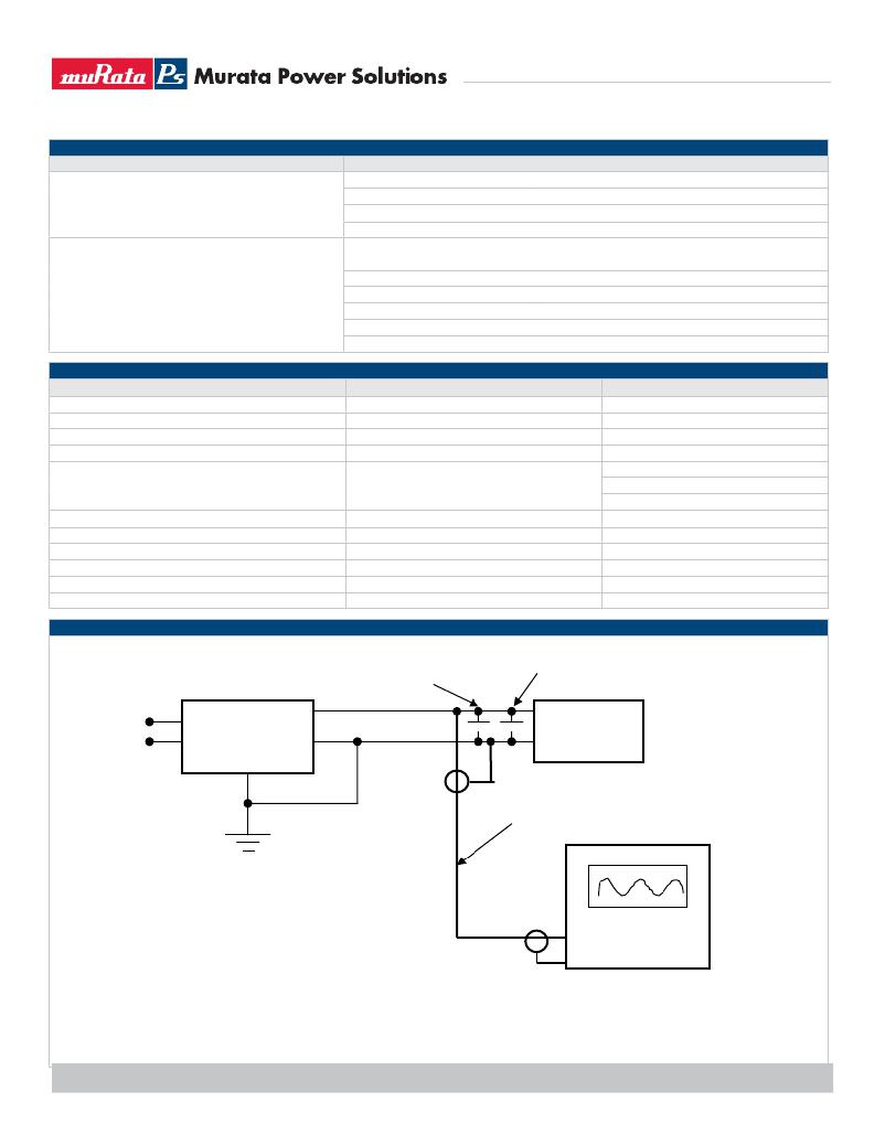
RIPPLE TEST SETUP
Conditions
Off
Flashing Yellow
Flashing Green
Green
Status
Output Fault
12V Output
12V
Fan1 Monitor
Fan2 Monitor
Description
IEC/EN 61000-3-2
IEC/EN 61000-3-3
FCC 47 CFR Parts 15/CISPR 22/EN55022
FCC 47 CFR Parts 15/CISPR 22/EN55022
IEC/EN 61000-4-2
IEC/EN 61000-4-3
IEC/EN 61000-4-4
IEC/EN 61000-4-5
IEC/EN 61000-4-6
IEC/EN 61000-4-8
IEC/EN 61000-4-11
Description
No AC input to all PS
Power Supply Failure
Main Output Absent
Power Supply Good
PS-ON, PGOOD, ACOK, PS_BAD, FANFAIL, OT Warning &
shutdown, AC Range
12V OV, 12V UV, 12V OC, Vsb Fail, Fan1 Fail, Fan2 Fail
8 bit scaled output voltage
8 bit scaled output current
8 bit scaled output current
8 bit scaled output current
Criteria
Class A, 6dB margin
Class A, 6dB margin
4kV contact discharge
8kV operational air discharge
15kV non-operational air discharge
1kV/2kV, Performance Criteria B
3 Vac, 80% AM, 1kHz, Performance Criteria A
3 A/m
Power Supply
2x270uF OSCON
0.1uF Ceramic
Load Box
AC Phase
AC Ground
BNC to BNC Shielded Cable
General Notes:
1. Load the outputs at specified minimum
output current.
2. Connect the probe as shown with the
input tip and ground as short as possible.
Oscilloscope
20MHz BW
3. Take all measurements
4. Repeat the measurements with the
outputs at specified maximum output
current.
CPS_D1U-W-1200-12-Hx.C10 Page 3 of 7
发布紧急采购,3分钟左右您将得到回复。
相关PDF资料
D1U-W-1200-48-HC2C
POWER SUPPLY 1200W AC/DC 48V
D1U-W-1600-12-HA2C
POWER SUPPLY 1600W AC/DC 12V
D1U-W-1600-48-HA2C
POWER SUPPLY 1600W AC/DC 48V
D1U2-W-400-12-HA4C
AC/DC FRONT END 400W 12V 5V AUX
D1U3CS-W-1200-12-HC3C
AC/DC FRNT END 1200W 12V 3.3V AX
D1U3CS-W-850-12-HC4C
AC/DC FRNT END 850W 12V 3.3V AUX
D1U4-W-1200-12-HC2C
POWER SUPPLY 1200W AC/DC 12V
D1U4-W-1600-12-HA2C
POWER SUPPLY 1600W AC/DC 12V
相关代理商/技术参数
D1U-W-1200-12-HC1C
功能描述:线性和开关式电源 900W at 110Vac 12V Front to Back Airflo RoHS:否 制造商:TDK-Lambda 产品:Switching Supplies 开放式框架/封闭式:Enclosed 输出功率额定值:800 W 输入电压:85 VAC to 265 VAC 输出端数量:1 输出电压(通道 1):20 V 输出电流(通道 1):40 A 商用/医用: 输出电压(通道 2): 输出电流(通道 2): 安装风格:Rack 长度: 宽度: 高度:
D1U-W-1200-12-HC2C
功能描述:线性和开关式电源 AC/DC 1200W 12V Main 3.3V Standby
RoHS:否 制造商:TDK-Lambda 产品:Switching Supplies 开放式框架/封闭式:Enclosed 输出功率额定值:800 W 输入电压:85 VAC to 265 VAC 输出端数量:1 输出电压(通道 1):20 V 输出电流(通道 1):40 A 商用/医用: 输出电压(通道 2): 输出电流(通道 2): 安装风格:Rack 长度: 宽度: 高度:
D1U-W-1200-48-HA1C
功能描述:线性和开关式电源 900W at 110Vac 12V Front to Back Airflo RoHS:否 制造商:TDK-Lambda 产品:Switching Supplies 开放式框架/封闭式:Enclosed 输出功率额定值:800 W 输入电压:85 VAC to 265 VAC 输出端数量:1 输出电压(通道 1):20 V 输出电流(通道 1):40 A 商用/医用: 输出电压(通道 2): 输出电流(通道 2): 安装风格:Rack 长度: 宽度: 高度:
D1U-W-1200-48-HA2C
功能描述:线性和开关式电源 AC/DC 1200W 48V Main 5V Standby RoHS:否 制造商:TDK-Lambda 产品:Switching Supplies 开放式框架/封闭式:Enclosed 输出功率额定值:800 W 输入电压:85 VAC to 265 VAC 输出端数量:1 输出电压(通道 1):20 V 输出电流(通道 1):40 A 商用/医用: 输出电压(通道 2): 输出电流(通道 2): 安装风格:Rack 长度: 宽度: 高度:
D1U-W-1200-48-HB1C
功能描述:线性和开关式电源 900W at 110Vac 12V Front to Back Airflo RoHS:否 制造商:TDK-Lambda 产品:Switching Supplies 开放式框架/封闭式:Enclosed 输出功率额定值:800 W 输入电压:85 VAC to 265 VAC 输出端数量:1 输出电压(通道 1):20 V 输出电流(通道 1):40 A 商用/医用: 输出电压(通道 2): 输出电流(通道 2): 安装风格:Rack 长度: 宽度: 高度:
D1U-W-1200-48-HB2C
功能描述:线性和开关式电源 AC/DC 1200W 48V Main 12V Standby RoHS:否 制造商:TDK-Lambda 产品:Switching Supplies 开放式框架/封闭式:Enclosed 输出功率额定值:800 W 输入电压:85 VAC to 265 VAC 输出端数量:1 输出电压(通道 1):20 V 输出电流(通道 1):40 A 商用/医用: 输出电压(通道 2): 输出电流(通道 2): 安装风格:Rack 长度: 宽度: 高度:
D1U-W-1200-48-HC1C
功能描述:线性和开关式电源 900W at 110Vac 12V Front to Back Airflo RoHS:否 制造商:TDK-Lambda 产品:Switching Supplies 开放式框架/封闭式:Enclosed 输出功率额定值:800 W 输入电压:85 VAC to 265 VAC 输出端数量:1 输出电压(通道 1):20 V 输出电流(通道 1):40 A 商用/医用: 输出电压(通道 2): 输出电流(通道 2): 安装风格:Rack 长度: 宽度: 高度:
D1U-W-1200-48-HC2C
功能描述:线性和开关式电源 AC/DC 1200W 48V Main 3.3V Standby
RoHS:否 制造商:TDK-Lambda 产品:Switching Supplies 开放式框架/封闭式:Enclosed 输出功率额定值:800 W 输入电压:85 VAC to 265 VAC 输出端数量:1 输出电压(通道 1):20 V 输出电流(通道 1):40 A 商用/医用: 输出电压(通道 2): 输出电流(通道 2): 安装风格:Rack 长度: 宽度: 高度:
